
WaveShare E-Ink Display

E-Paper

I really like e-paper as a concept. Gentle on the eyes, holds an image with no power. So a long time ago I purchased a 4.3" WaveShare e-paper display and did nothing with it. It is quite a large display, 800x600 pixels and, despite the passage of many years since I bought it, still quite expensive at $121 from core-electronics.

/images/arduino/epaper-hello.jpg

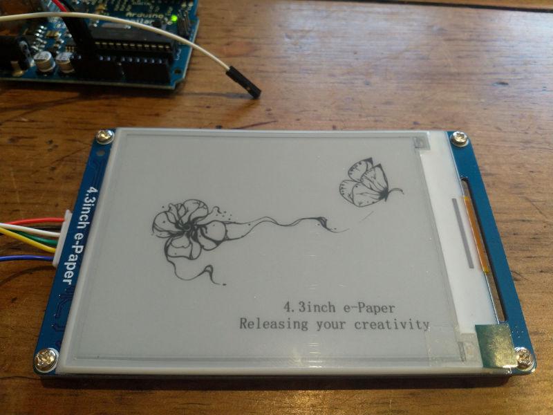
Shown here with the pretty picture of a butterfly and a flower as it comes out of the box. Note also that I have it oriented in landscape with the wires on the left, more on this later.

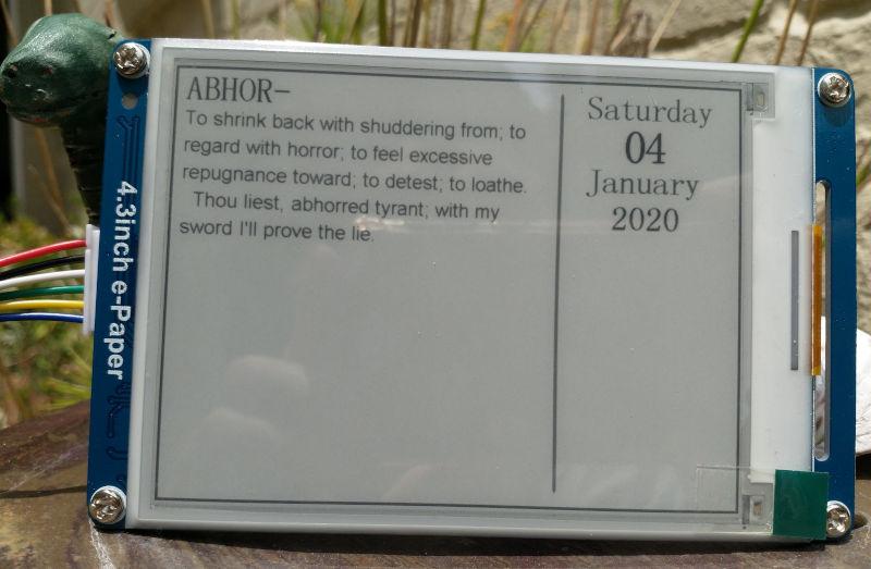
I thought I'd try to put together a word-a-day e-paper calendar for the kitchen table, as I also like words.

First thing to do is to find some a sample word for which end I found Websters Unabridged Dictionary on Gutenberg.

Abhor

To shrink back with shuddering from; to regard with horror; to feel excessive repugnance toward; to detest; to loathe. Thou liest, abhorred tyrant; with my sword I'll prove the lie.

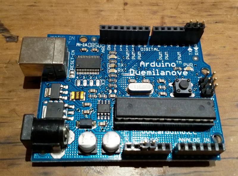
Connecting To The Arduino

The display has six wires. The documentation suggests that the blue (RST) wire does not need to be connected. In practice I found that it is better to not connect the white wire as well.

If the white wire is connected then it is not possible to upload a sketch as an error occurs:

avrdude: stk500_getsync() attempt 1 of 10: not in sync: resp=0xa5

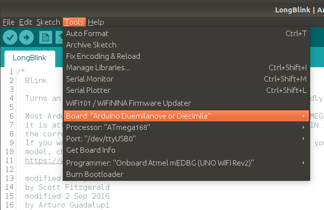
The documentation suggests that you disconnect the green and white wires (RX and TX) while uploading a sketch. The you have to press the reset button to start the sketch again. If instead you just don't connect the white (RX) wire at all, everything works fine.

Wiring

Arduino

4.3" e-Paper

5v

Red

GND

Black

RX/D0

White*

TX/D1

Green

D2

Yellow

RST

Blue*

  • Don't connect the blue or white wires

E-Paper Hello World

Following is a basic hello world program that displays the butterfly and flower image that is in the internal memory.

epaper_hello.ino (Source)

#include <epd.h>
const int led = 13;
void setup() {
  /*
  user led init
  */
  pinMode(led, OUTPUT);
  digitalWrite(led, LOW);
  epd_init();
  epd_wakeup();
  epd_set_memory(MEM_NAND);
  epd_screen_rotation(EPD_INVERSION);
}
void loop() {
  // put your main code here, to run repeatedly:
  epd_clear();
  epd_disp_bitmap("PIC7.BMP", 0, 0);
  epd_udpate();
  epd_enter_stopmode();
  char flag = 0;
  while (1)
  {
    if(flag)
    {
      flag = 0;
      digitalWrite(led, LOW);
      delay(1000);
    }
    else
    {
      flag = 1;
      digitalWrite(led, HIGH);
      delay(3000);
    }
  }
}

Things to note:

  • line 13: epd_wakeup because we put it to sleep earlier. While it is awake it draws a fair amount of power.

  • line 15: set the screen orientation to landscape, with wires on the left

  • lines 21-23: clear the display, load a picture from the internal flash memory and update the display

  • line 25: epd_enter_stopmode so it stops drawing power. Note the red light at the top left turns off.

Then the on-board LED starts flashing again. Just so it is clear that there is something happening.
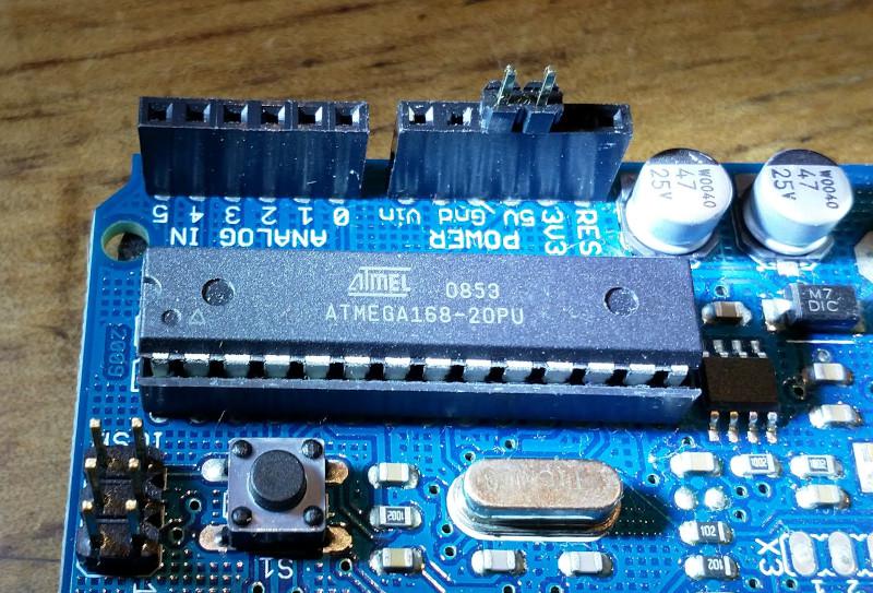
E-Paper Calendar

My vision of an epaper word-a-day calendar is a little more challenging than I had at first anticipated. The software for drawing to the display is extremely rudimentary, with commands to display text, an image from the SD card or internal NAND flash and basic vector drawing commands.

void epd_draw_pixel(int x0, int y0);
void epd_draw_line(int x0, int y0, int x1, int y1);
void epd_fill_rect(int x0, int y0, int x1, int y1);
void epd_draw_circle(int x0, int y0, int r);
void epd_fill_circle(int x0, int y0, int r);
void epd_draw_triangle(int x0, int y0, int x1, int y1, int x2, int y2);
void epd_fill_triangle(int x0, int y0, int x1, int y1, int x2, int y2);
void epd_clear(void);

void epd_disp_char(unsigned char ch, int x0, int y0);
void epd_disp_string(const void * p, int x0, int y0);

void epd_disp_bitmap(const void * p, int x0, int y0);

There is also an exciting looking function for writing images to the SD card documented in the manual, but there are no library functions to use this functionality.

Send a file to the SD card using UART (0x40) After this command executed, any data from UART will be saved into the SD card and saved with the given filename. If the transmission stops more than 1s, this function will stop too. After the file sent, file size and Xor check will be returned and you should compare them to check if the file was sent properly. Last, if the file was sent properly, you should send the character ‘y’ to confirm. If the file is an image (.JPG or .BMP), you should set the storage area to SD card (A5 00 0A 07 01 CC 33 C3 3C A9), and then use the display image command to display it. UART input stream command is not affected by the storage area settings.Files are only going to be saved into the Micro SD card.

Nevertheless I laboriously laid out a basic mockup of a calendar page. While laying this out I used a grid of points to help align the text.

/**
* Draw a grid from (t,l) with points spaced `w` pixels apart and with
* major `tick` marks as specified.
*/
void draw_grid(int t, int l, int w, int tick) {
  int i = 0;
  int j = 0;
  for (int x = l; x <= 800; x += w) {
    i++;
    for (int y = t; y <= 600; y += w) {
      j++;
      epd_draw_pixel(x, y);
      if ((i % tick == 0) && (j % tick == 0)) {
        draw_tick(x, y);
      }
    }
  }
}

The finished sample:

/images/arduino/epaper-calendar.jpg

The code:

epaper_calendar.ino (Source)

#include <epd.h>
const int led = 13;
void setup() {
  /*
  user led init
  */
  pinMode(led, OUTPUT);
  digitalWrite(led, LOW);
  // random number seeding
  Serial.begin(9600);
  // if analog input pin 0 is unconnected, random analog
  // noise will cause the call to randomSeed() to generate
  // different seed numbers each time the sketch runs.
  randomSeed(analogRead(0));
  epd_init();
  epd_wakeup();
  epd_set_memory(MEM_NAND);
  epd_screen_rotation(EPD_INVERSION);
}
void loop() {
  char flag = 0;
  draw_calendar();
  epd_enter_stopmode();
  while (1)
  {
    if(flag)
    {
      flag = 0;
      digitalWrite(led, LOW);
      delay(1000);
    }
    else
    {
      flag = 1;
      digitalWrite(led, HIGH);
      delay(3000);
    }
  }
}
void draw_calendar(void) {
  char const *date[] = {"Saturday", "04", "January", "2020"};
  char const *title = " ABHOR-";
  char const *words[] = {
    "To shrink back with shuddering from; to",
    "regard with horror; to feel excessive",
    "repugnance toward; to detest; to loathe.",
    "  Thou liest, abhorred tyrant; with my ",
    "sword I'll prove the lie."
  };
  epd_clear();
  // draw the word of the day
  epd_set_color(BLACK, WHITE);
  epd_set_en_font(ASCII48);
  epd_disp_string(title, 8, 8);
  // draw the definition
  epd_set_en_font(ASCII32);
  epd_set_color(DARK_GRAY, WHITE);
  for (int i=0; i<5; i++) {
    epd_disp_string(words[i], 16, 58 + (38 * i));
  }
  // draw the date
  epd_set_color(DARK_GRAY, WHITE);
  epd_set_en_font(ASCII48);
  epd_disp_string(date[0], 578, 13);
  epd_set_color(BLACK, WHITE);
  epd_set_en_font(ASCII64);
  epd_disp_string(date[1], 633, 59);
  epd_set_color(DARK_GRAY, WHITE);
  epd_set_en_font(ASCII48);
  epd_disp_string(date[2], 578, 117);
  epd_set_color(BLACK, WHITE);
  epd_disp_string(date[3], 616, 169);
  // draw a decorative border around the screen
  for (int i=0; i < 4; i++) {
    epd_set_color(DARK_GRAY, WHITE);
    draw_rect(i, i, 799 - (2*i), 599 - (2*i));
  }
  // draw a light gray round ended line between the date and the word of the day
  for (int i=0; i < 5; i++) {
    int h = abs(i-2) * 2;
    epd_set_color(GRAY, WHITE);
    epd_draw_line(540 + i, 18 + h, 540 + i, 578 - h);
  }
  // draw_grid(8, 8, 10, 5);
  epd_udpate();
}
void draw_rect(int t, int l, int h, int w) {
  epd_draw_line(t, l, t, l + w);
  epd_draw_line(t, l, t + h, l);
  epd_draw_line(t + h, l, t + h, l + w);
  epd_draw_line(t, l + w, t + h, l + w);
}
/**
* Draw a grid from (t,l) with points spaced `w` pixels apart and with
* major `tick` marks as specified.
*/
void draw_grid(int t, int l, int w, int tick) {
  int i = 0;
  int j = 0;
  for (int x = l; x <= 800; x += w) {
    i++;
    for (int y = t; y <= 600; y += w) {
      j++;
      epd_draw_pixel(x, y);
      if ((i % tick == 0) && (j % tick == 0)) {
        draw_tick(x, y);
      }
    }
  }
}
/**
* Draw a major tick mark at the point specified.
*/
void draw_tick(int x, int y) {
  epd_draw_pixel(x - 1, y);
  epd_draw_pixel(x + 1, y);
  epd_draw_pixel(x, y - 1);
  epd_draw_pixel(x, y + 1);
}

Clearly this project needs a higher level text layout capability. An interesting solution to this problem is to build an image on a remote server and then chop it into scanlines which are then delivered piecemeal over wifi.

Resources

Getting Started With Arduino

Arduino Programming

I have an old Arduino Duemilanove board that I bought a long time ago and have since neglected.

This is a very old board, first released in 2009 and no longer available except maybe on Ebay.

/images/arduino/arduino-duemilanove.jpg

To get started with using this microcontroller you have to download the Arduino IDE.

Arduino IDE

Download the Arduino IDE and install. It is likely that you will have to add your user account to the dialout group and log in again. I also had to make the /dev/ttyUSB0 device group read+write-able. There may be other ways to do this but I used reliable old chmod g+rw /dev/ttyUSB0.

A good hello world project is to upload the blink sketch. This makes the onboard LED flash, which confirms that you are able to do something with the microcontroller.

I modified the sketch slightly to make the LED stay on for three seconds, just to be sure .

/*
  Blink

  Turns an LED on for three seconds, then off for one second, repeatedly.

  http://www.arduino.cc/en/Tutorial/Blink
*/

// the setup function runs once when you press reset or power the board
void setup() {
  // initialize digital pin LED_BUILTIN as an output.
  pinMode(LED_BUILTIN, OUTPUT);
}

// the loop function runs over and over again forever
void loop() {
  digitalWrite(LED_BUILTIN, HIGH);   // turn the LED on (HIGH is the voltage level)
  delay(3000);                       // wait for a second
  digitalWrite(LED_BUILTIN, LOW);    // turn the LED off by making the voltage LOW
  delay(1000);                       // wait for a second
}

Click the Verify (tick mark) and Upload (right arrow) buttons and the sketch should upload to the board and the LED should start blinking.

/images/arduino/arduino-ide-closeup.png

Trouble

I had a lot of trouble getting this to work at all. There are a lot of basic things that you have to get right.

  • As mentioned, fix group access permissions to the USB device.

  • Make sure you have selected the right board from the Tools > Board menu, it won't be auto-detected for you.

/images/arduino/arduino-ide.png
  • Select the right processor from the Tools > Processor menu. It might help to have a close look at the chip on the board to work out which one it is.

/images/arduino/arduino-duemilanove-closeup.jpg
  • If this all fails, you can turn on additional debugging output from File > Preferences > Show Verbose Output and start searching Stack Overflow.

Welcome Helianthi

Happy New Year

A New Laptop For A New Year

I went to JB Hi-Fi and after much indecision and wandering up and down the aisles, bought an HP Laptop. As I was planning to use it for Linux and probably wanted dual boot with Windows, I selected one with a larger hard disk drive.

I played with Windows 10 on the laptop and was gripped by buyer's remorse. I became quite grumpy. What was I going to do with this thing? After fiddling with a few settings to make it feel more homely and not succeeding much I set about installing Linux.

I took the easy choice and decided on Ubuntu, downloaded the Ubuntu 18.04.3 LTS via bittorrent and flashed it onto a USB stick.

Make Some Room

The Ubuntu installation is smoother if there is an empty disk partition for it. The last thing I did in Windows was to use the Disk Manager to shrink the main disk volume.

Booting To BIOS

The next step was to restart and press the escape key while restarting. This shows a menu that lets you press [F10] to get into the BIOS. In the BIOS you need to disable secure boot.

Install From USB

Installing Ubuntu from the USB stick proved to be very smooth. It was just a matter of clicking the buttons and waiting. Almost all the hardware was supported by default.

Installing Drivers For Wifi Card

There is one little bit of traditional Linux software tinkering. The laptop turns out to have a wifi card that is not supported by the default install of Ubuntu.

First, to find the make of the wireless card:

$ lspci -v | grep -i network
03:00.0 Network controller: Realtek Semiconductor Co., Ltd. RTL8821CE 802.11ac PCIe Wireless Network Adapter
  Subsystem: Hewlett-Packard Company RTL8821CE 802.11ac PCIe Wireless Network Adapter

This particular Realtek model (RTL8821CE) required an alternate driver.

First, prepare to install some software:

$ sudo apt-get install linux-headers-generic build-essential git dkms

Install Realtek Driver

The driver for this wireless card is maintained by Tomás Pinho. The software must be downloaded and installed, but this is straightforward:

$ git clone http://github.com/tomaspinho/rtl8821ce
$ cd rtl8821ce/
$ chmod +x dkms*.sh
$ sudo ./dkms-install.sh
$ sudo reboot

Reboot and configure your wireless adapter.